Product Category
Contact Us
Phone:
86-577-86569666/85986466
Fax: 86-577-85888877
Email: zgkk@zgkkv.com
Agent Hotline: 86-18523831111
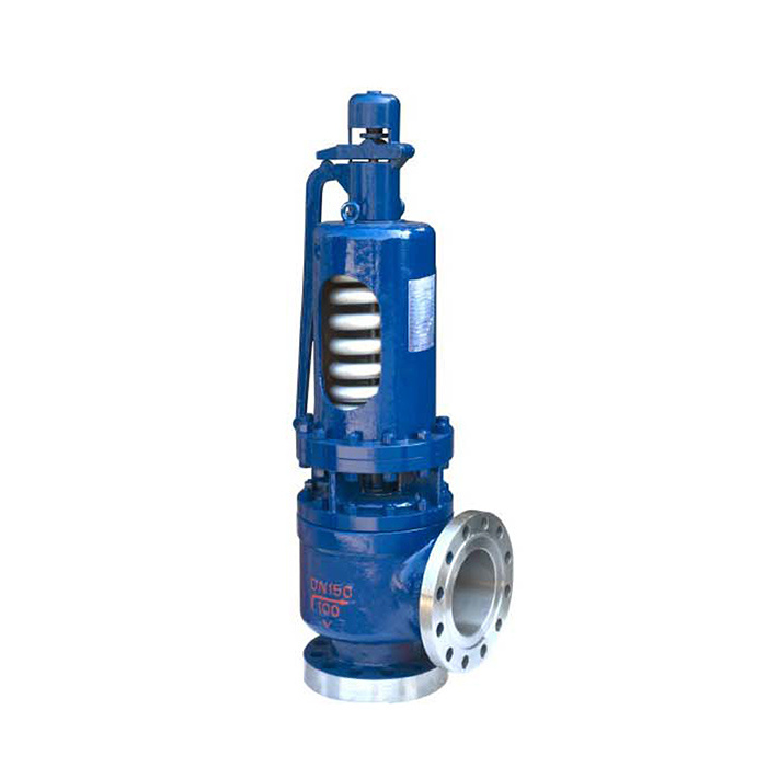
Spring Full Bore Type Safety Valve (W Series)
Key words:
Classification:
Keyword: Spring Full Bore Type Safety Valve (W Series)
E-mail:
Details
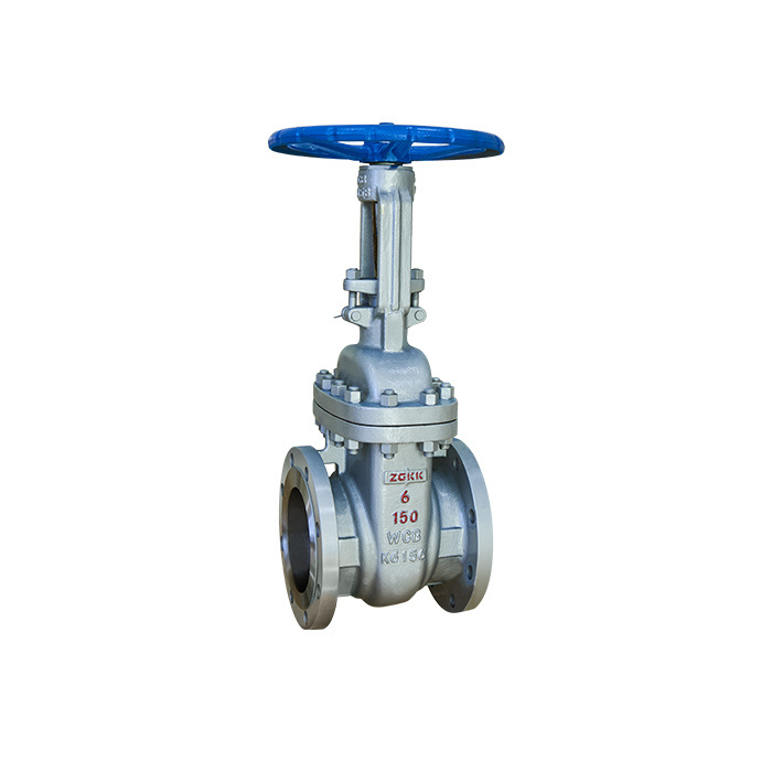
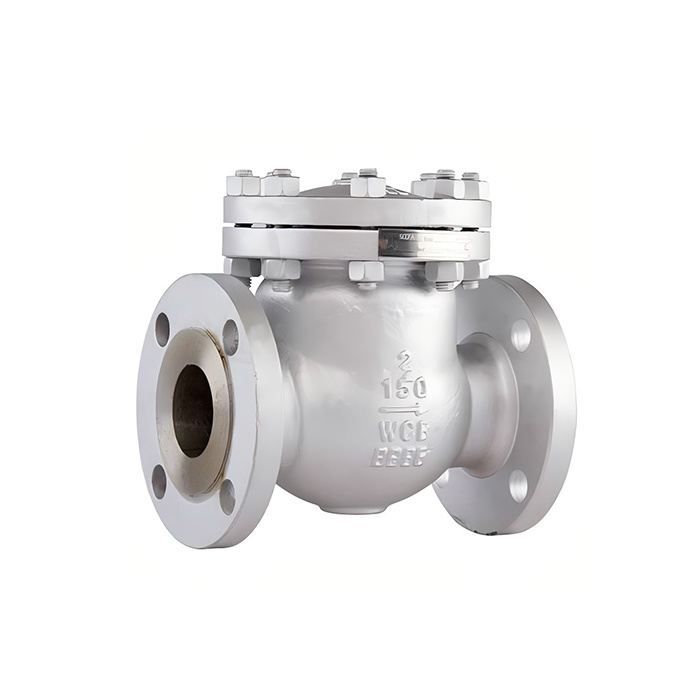
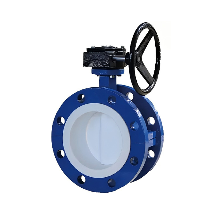
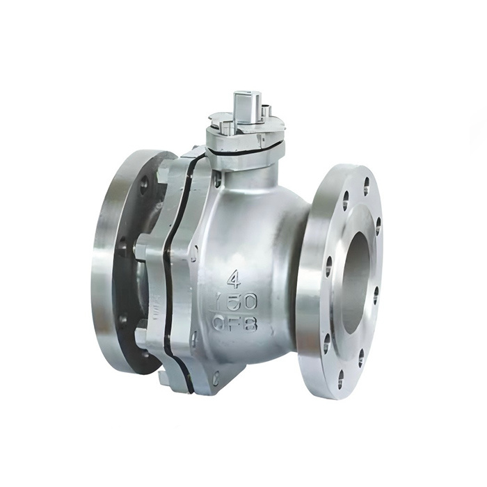
Our products now cover a wide range of standardized fluid control products that can be adapted to a variety of drive modes, comprising ball valves, butterfly valves, gate valves, globe valves, check valves, safety valves, rotary ball valves, plunger valves etc. Our products are widely used in water conservancy, municipal, electric power, gas, petrochemical, coal chemical, energy, environmental protection, medicine, real estate, metallurgy, mining and many other fields.
A48Y-C tvoe applicable temperalure are less than 425℃: A48Y-V type is suitable for the exceeding pressure proective equipment, their workingtemperalure is 550℃ orless. Such as the boller used in powerstation,pressure ontainer,pressure reducing and femperature reducing machine.
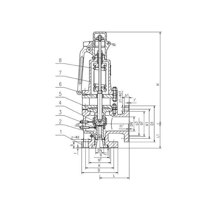
Main External and Connecting Dimensions
| Type | DN Nominal diameter |
Connecting dimensions(mm) | |||||||||||||
| L | Li | H | D | D1 | D2 | b | Z-φd | DN1 | D' | D1 | D2 | b' | Z¹-φd | ||
| A48Y-P543.82V | 65 | 190 | 190 | 853 | 220 | 170 | 110 | 50 | 8-25 | 150 | 300 | 250 | 204 | 30 | 8-25 |
| A48Y-10 | 80 | 190 | 190 | 853 | 230 | 180 | 121 | 50 | 8-25 | 150 | 300 | 250 | 204 | 30 | 8-25 |
| A48Y-10 | 65 | 190 | 190 | 853 | 220 | 170 | 110 | 50 | 8-25 | 150 | 300 | 250 | 204 | 30 | 8-2 |
| A48Y-P543.82V | 80 | 190 | 190 | 853 | 230 | 180 | 121 | 50 | 8-25 | 150 | 300 | 250 | 204 | 30 | 8-2 |
| A48Y-20 | 65 | 210 | 210 | 933 | 260 | 203 | 97 | 55 | 830 | 150 | 300 | 250 | 204 | 30 | 8-2 |
| A48Y-P545.29V | 65 | 210 | 210 | 933 | 260 | 203 | 97 | 55 | 8-30 | 150 | 300 | 250 | 204 | 30 | 8-2 |
| A48Y-20 | 80 | 210 | 210 | 933 | 260 | 203 | 116 | 60 | 8-34 | 150 | 300 | 250 | 204 | 30 | 8-25 |
| A48Y-P545.29V | 80 | 210 | 210 | 933 | 290 | 230 | 116 | 60 | 8-34 | 150 | 300 | 250 | 204 | 30 | 8-25 |
| A48Y-20 | 80 | 210 | 210 | 933 | 290 | 230 | 116 | 60 | 8-34 | 150 | 300 | 250 | 204 | 30 | 8-25 |
| A48Y-Ps410V | 80 | 210 | 210 | 933 | 290 | 230 | 116 | 60 | 8-34 | 150 | 300 | 250 | 204 | 30 | 8-25 |
Instruction
This valve is used for power plant bollers, pressure containers, pressure and temperature reducing devices and other faciliies. t serves to ensure the safety of the device during working.
Structure Briefing
1. The main characteristics of the spring fully bore type safety valve are: simple structure, good seal performance, accurate opening pressure,largedischarge capability, low differential reseating pressure and convenient adjustment, etc.
2. Seat type seat: t is the Laware Seattype seat. The speed ofthe steam reaches the velocity of sound when passing the exit way of the seatl; thesealed surace of the seat at is made of hard alloy of cobalt by overlaving welding., Large discharge coeficient, fine abiites of anti fricion anccorrosion resistance and long durability are recognzed.
3. Thermo elastic disc: the disc is of thermo dlastic sturcture. Taking the advantage of its minor out-of shape fea-Ure when under the mediumpressure, the seal ability has been raised, and the problem that pre-discharge phenomenon of the safety valve happens when the mediumpressure approaching the set pressure has been overcome. The sealed surface of the disc has adopted the advanced techology of laser healhardening to increase the hardness and the ability of anti-friction and corrosion sistance.
4. Upper adjusting ring: the valve can acquire appropriate reseaing pressure by adlusting the upper adjusting ring to change the flow direc-ion othe medium discharged from the seat.
5. Lower adjusting ring: the valve can rapidly reach full bore in the discharging process by adjusting the adjusting ring.
6. Back pressure adjusting sleeve: it is an auxliary apparatus that serves to adjust the back pressure ofthe disc o acquire appropriate dif-ferentialreseating pressure.
Instahation Instruction
1. The safely valve shall be installed vertically and it would be belter to installthe valve direclly upon the adaptor of the container or the pipe. Theinside diameter of the adaptor shall be no less than that of the inlet pipe of the safety valve.
2. To avoid the thermal stress that is caused by the thermal expansion of the discharge pipe, the exit way of the safely valve shallbe equipped withappropriate expansion joint. The inside diameter of the dis-charge pipe should larger than the diameter of the exit way ofthe valve. ts length shallbe as short as possible and no bent isallowed. The weight of both the discharge pipe and the expansion joint shall not be applied to thesafelyvalve, and they shall be fastened upon the con-struction. The distance between both centerlines ofthe discharge pipe and the valve body shall beas short as possible.
3. The exit way of the mufler shall have enough area, in order to avord producing back pressure that would affect the discharge capability of thevalve.
4. Water drainage pipes shall be installed atthe ends of both the exhaust pipe and the body; the exit of the back pressure adjusting sleeve shal beequipped with short bend.
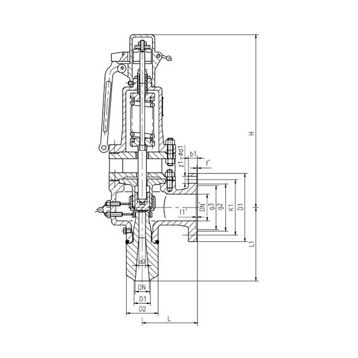
Main External and Connecting Dimensions
| Type | DN Nominal diameter | Dimensions(mm) | |||||||||
| L | Li | D0 | H | DN' | D | D1' | D2' | B' | z-d | ||
| A68Y-20 | 65 | 210 | 290 | 48 | 923 | 150 | 300 | 250 | 204 | 30 | 8-25 |
| A68Y-P5410V | 65 | 210 | 290 | 48 | 923 | 150 | 300 | 250 | 204 | 30 | 8-25 |
| A68Y-20 | 80 | 210 | 290 | 52 | 923 | 150 | 300 | 250 | 204 | 30 | 8-25 |
| A68Y-P5410V | 80 | 210 | 290 | 52 | 923 | 150 | 300 | 250 | 204 | 30 | 8-25 |
| A68Y-25 | 65 | 210 | 290 | 48 | 923 | 150 | 300 | 250 | 204 | 30 | 8-25 |
| A68Y-Ps414V | 65 | 210 | 290 | 48 | 923 | 150 | 300 | 250 | 204 | 30 | 8-25 |
| A68Y-25 | 80 | 210 | 290 | 52 | 1003 | 150 | 300 | 250 | 204 | 30 | 8-25 |
| A68Y-P5414V | 80 | 210 | 290 | 52 | 1003 | 150 | 300 | 250 | 204 | 30 | 8-25 |
| A68Y-32 | 65 | 210 | 290 | 48 | 1083 | 150 | 300 | 250 | 204 | 30 | 8-25 |
| A68Y-P5420V | 65 | 210 | 290 | 48 | 1083 | 150 | 300 | 250 | 204 | 30 | 8-25 |
| A68Y-32 | 80 | 210 | 290 | 52 | 1083 | 150 | 300 | 250 | 204 | 30 | 8-25 |
| A68Y-P5420V | 80 | 210 | 290 | 52 | 1083 | 150 | 300 | 250 | 204 | 30 | 8-25 |
| A68Y-10 | 150 | 310 | 525 | 100 | 1158 | 300 | 485 | 430 | 390 | 36 | 16-30 |
| A68Y-P543.82V | 150 | 310 | 525 | 100 | 1158 | 300 | 485 | 430 | 390 | 36 | 16-30 |
| A68Y-10 | 200 | 310 | 525 | 125 | 1158 | 300 | 485 | 430 | 390 | 36 | 16-30 |
| A68Y-Ps42.5V | 200 | 310 | 525 | 125 | 1158 | 300 | 485 | 430 | 390 | 36 | 16-30 |
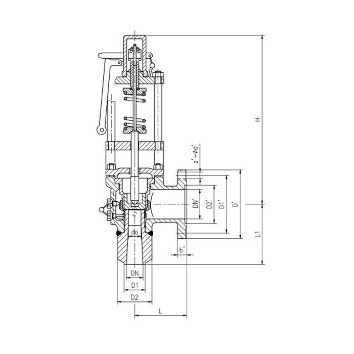
Main Connecting Dimensions
| Type | DN Nominal diameter |
Dimensions(mm) | ||||||||
| L | Li | D0 | DN' | D | D1' | D2' | B' | z¹-d | ||
| A68E210/550V1 | 65 | 240 | 280 | 46 | 100 | 265 | 210 | 150 | 38 | 8-30 |
| A68SB160/440C1 | 65 | 260 | 280 | 52 | 150 | 320 | 250 | 204 | 30 | 8-25 |
| A68E210/400C1 | 80 | 190 | 305 | 58 | 150 | 340 | 280 | 204 | 38 | 8-34 |
| A68E210/550V1 | 80 | 190 | 305 | 58 | 150 | 340 | 280 | 204 | 38 | 8-34 |
| A68E210/550V2 | 80 | 190 | 305 | 60 | 150 | 300 | 250 | 204 | 30 | 8-25 |
| A68E160/550V1 | 100 | 320 | 340 | 70 | 250 | 445 | 385 | 313 | 42 | 12-34 |
| A68SB100V1 | 100 | 260 | 325 | 80 | 150 | 300 | 250 | 204 | 30 | 8-25 |
| A68SB100V2 | 100 | 260 | 325 | 85 | 150 | 300 | 250 | 204 | 30 | 8-25 |
| A68SB100C1 | 150 | 305 | 385 | 115 | 250 | 445 | 385 | 313 | 42 | 12-34 |
| A68SB100C2 | 150 | 305 | 385 | 110 | 250 | 445 | 385 | 313 | 42 | 12-34 |
| A68SB100C3 | 150 | 305 | 385 | 120 | 250 | 445 | 385 | 313 | 42 | 12-34 |
| A68SB100V1 | 150 | 305 | 385 | 115 | 250 | 445 | 385 | 313 | 42 | 12-34 |
| A68SB100V2 | 150 | 305 | 385 | 100 | 250 | 445 | 385 | 313 | 42 | 12-34 |
| A68SC2500C2 | 11/2"(40) | 155 | 165 | 18 | Exit"3×300Lb | |||||
| A68SC150011 | 2"(50) | 216 | 280 | 33 | Exit"6×300Lb | |||||
| A68SC1500C1 | 21/2"(65) | 216 | 280 | 40 | Fxit"6×300Lb | |||||
| A68SC1500C2 | 21/2"(65) | 216 | 305 | 46 | Fxit"6×300Lb | |||||
Related Products
Message
*Leave your contact information to get a free product quote

